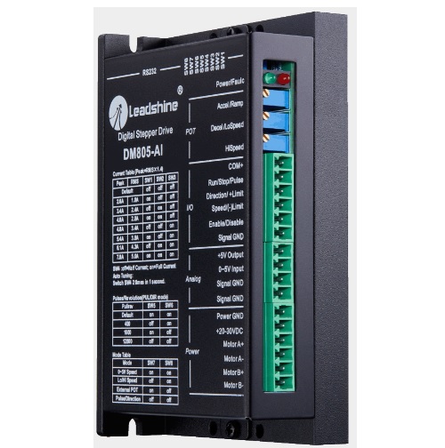
Advanced Microstepping Stepper drive, DM805-AI
Product Description
Advanced Microstepping Stepper drive, DM805-AI
- Extra-low motor noise offers excellent quietness
- Analogue signal (0-5V) for speed control
- Step & direction control signals also acceptable
- Internal step generator for no motion controller system
- Built-in 5V output for an analogue control and testing
- Built-in potentiometers for speed, acceleration and deceleration adjusting
- Limit signal input for safe operation
- Anti-resonance and low-speed ripple smoothing
- Supply voltage up to 80 VDC
- Output current programmable, from 0.5A to 7.0A
Electrical Specifications
|
Parameter |
Min |
Typical |
Max |
Unit |
|
Input Voltage |
18 |
60 |
80 |
VDC |
|
Pulse Input Frequency |
0 |
- |
200 |
kHz |
|
Logic Signal Current |
7 |
10 |
16 |
mA |
|
Isolation Resistance |
500 |
- |
- |
MΩ |
Velocity Control
|
Item |
Specification |
Dead Band |
Resolution |
Min |
Max |
|
|
Analogue Input |
0-5V Speed Mode |
0-5 V |
10 mV |
10 mV |
0 Rev/s |
25 ± 0.5 Rev/s |
|
External POT Mode |
20 mV |
|||||
|
Accel / Decel / Ramp Potentiometer |
0-25 turns |
10 mV |
10 mV |
0.5 Rev/s2 |
250 ± 1Rev/s2 |
|
|
LoSpeed Potentiometer |
0-25 turns |
10 mV |
10 mV |
0 Rev/s |
5 ± 0.01Rev/s |
|
|
HiSpeed Potentiometer |
0-25 turns |
10 mV |
10 mV |
0 Rev/s |
25 ± 0.5 Rev/s |
|
Operating Environment
| Cooling |
Natural Cooling or Forced cooling |
|
| Operating Environment | Environment | Avoid dust, oil fog and corrosive gases |
| Storage Temperature | -20 °C - 65 °C (-4°F - 149 °F ) | |
| Ambient Temperature | 0°C- 50 °C (32 °F- 122°F) | |
| Humidity | 40%RH - 90%RH | |
| Operating Temperature (Heat Sink) | 70 °C (158 °F) Max | |
| Vibration | 10-55Hz, 0.15mm/s | |
| Storage Temperature |
-20 °C- 65 °C (-4 °F- 149 °F ) |
|
|
Digital I/O Signal Connector |
|||
| 6-pin screw terminal, 3.81 mm space | |||
|
Pin |
Name |
I/O |
Description |
|
1 |
COM+ |
Power |
+5V Power Input, common reference of all inputs |
|
2 |
Run/Stop/Pulse |
I |
Run/Stop signal for 0-5V analogue, Lo/Hi Speed and External POT mode. In Pulse/Direction mode, it accepts pulse input. |
|
3 |
Direction / +Limit |
I |
Direction input for 0-5V analogue, Lo/Hi Speed and Pulse/Direction mode. It is the +limit switch input in External POT mode. When +Limit is activated, the motor speed decelerates to zero in the acceleration set by Ramp potentiometer. The +Limit is only activated when the voltage applied to 0-5V input is 2.5-5V. |
|
4 |
Speed / (-)Limit |
I |
Speed selection input in Lo/Hi speed mode. It is the -limit switch input in External POT and 0-5V Speed mode. When +Limit is activated, the motor speed decelerates to zero in the acceleration set by Ramp potentiometer. In External POT mode, the –Limit is activated only when the voltage applied to 0-5V input is 0-2.5V. In 0-5V speed mode, the –Limit is activated only when Direction input is connected to Signal GND. |
|
5 |
Enable / Disable |
I |
This signal is used to enable or disable the power stage. Usually left it unconnected to enable the power stage. |
|
6 |
Signal GND |
GND |
Signal ground. It is common with the power ground. |
|
Analogue Signal Connector |
|||
| 4-pin screw terminal, 3.81 mm space | |||
|
Pin |
Name |
I/O |
Description |
|
1 |
+5V Output |
O |
+5V Power Output, reference to signal ground |
|
2 |
0-5V Input |
I |
Analogue 0-5V reference input |
|
3 |
Signal GND |
GND |
Signal ground. It is common with the power ground. |
|
4 |
Signal GND |
GND |
Signal ground. It is common with the power ground. |
|
Power Connector |
|||
| 6-pin screw terminal, 3.81 mm space | |||
|
Pin |
Name |
I/O |
Description |
|
1 |
Power GND |
GND |
Power ground |
|
2 |
+20-80VDC |
I |
Power supply input, 24-72VDC recommended, leaving rooms for voltage fluctuation and back-EMF. |
|
3 |
Motor A+ |
O |
Motor Phase A+ |
|
4 |
Motor A- |
O |
Motor Phase A- |
|
5 |
Motor B+ |
O |
Motor Phase B+ |
|
6 |
Motor B- |
O |
Motor Phase B- |
Manual & Download:
One Year Warranty
Additional Details
 Updating...
