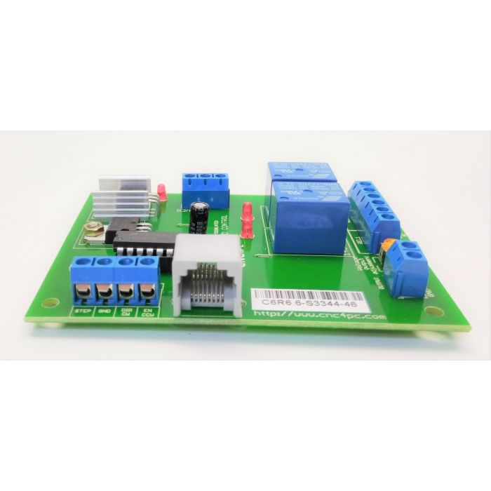
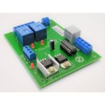
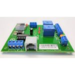
C6 – Variable Speed Control Board
Product Description
OVERVIEW
This card lets you control your spindle with step and direction signals, as if it was an axis motor. It convert the step signal to an analog (0-10VDC) and by using the onboard relays you can control the direction (CW/CCW) and enable the drive (On/Off). A Variable Frequency Drive or Inverter works by modifying the frequency for AC motors. You can control most of these devices with an external analog signal (0-10VDC). That is, if there is 5VDC coming into through the control signal, the motor will run at 50% of full speed, if there was 10VDC, the motor will run at 100% of full speed. If there is no signal coming out, then the motor will stop. This unit can also be used on many DC motor controllers by replacing the potentiometer that controls the speed.
FEATURES
- Inputs a frequency (step) and outputs an analog 0-10VDC.
- Have two relays that can be used to control the direction and enable and disable the drive.
- Opto-isolated output signals. The analog and CW and CCW signals are optically isolated, so this board can be used with drives that make grounds common with the mains that drive the VFD or motor.
- All TTL +5VDC or +3.3VDC Signals. Interface directly with parallel port interface products and other cnc4pc.com cards. 5VDC (TTL) signals are very common among automation devices.
- Flexible design. It works with cnc4pc’s products, directly through your parallel port, or through many other parallel port control products.
- RJ45 Connector. This connector is for connecting the boards directly using a standard RJ45 cable, allowing can be used to carry input signal and power line.
Wiring Minarik MM Series Speed Controller
Wiring the Speed Controller that comes with Sieg X3
FC250J (Wiring Diagram) / FC250J (Instructions)
Additional Details
 Updating...